Air Compressor Plumbing Diagram Setup and Installation Tips
An air compressor plumbing diagram is a visual guide that shows how all the pipes, fittings, and components connect in your compressed air system. This article walks you through reading diagrams, choosing the right parts, and installing your setup step by step. You will learn common mistakes to avoid and expert tips to keep your system running smoothly for years.
Setting up an air compressor plumbing diagram might feel overwhelming at first glance. All those lines, symbols, and connections can look like a foreign language. But once you understand the basics, the whole process becomes much simpler and even enjoyable. Whether you are a DIY enthusiast or a shop owner planning a new setup, knowing how your compressed air system is plumbed makes a huge difference.
A proper plumbing diagram shows you exactly where every pipe, valve, and fitting goes. It helps you avoid costly mistakes, reduce air leaks, and keep your system running efficiently. In this guide, we will break everything down into plain language. You will learn what each part means, how to plan your layout, and how to install it all step by step.
We will also cover common pitfalls and share maintenance tips that most guides skip. By the end, you will feel confident enough to tackle your own air compressor setup from start to finish. Let us dive in.
Key Takeaways
- Understand the diagram: A plumbing diagram maps out every connection, valve, and pipe in your compressed air system so you can install with confidence.
- Choose the right parts: Using proper fittings, pipe sizing, and connectors prevents leaks and ensures safe operation.
- Follow a step-by-step process: Planning, cutting, connecting, and testing each stage matters for a reliable setup.
- Avoid common mistakes: Skipping pressure testing, using wrong fittings, and ignoring pipe support are frequent errors that cause problems.
- Maintenance keeps it running: Regular inspections, draining, and fitting checks extend the life of your plumbing system.
- Know when to call a pro: Complex setups, high-pressure systems, and code compliance may require professional help.
📑 Table of Contents
What Is an Air Compressor Plumbing Diagram?
An air compressor plumbing diagram is a visual map of your entire compressed air system. It shows how the compressor, tank, pressure switch, regulator, and all the piping connect together. Think of it as a blueprint that tells you exactly what goes where.
These diagrams use standardized symbols to represent different components. A circle might stand for the compressor unit. Rectangles represent tanks or filters. Lines between them show the pipes and air flow paths. Once you learn the basic symbols, reading the diagram becomes second nature.
There are two main types of diagrams you will encounter. The first is a schematic diagram, which focuses on the functional connections. The second is a physical layout diagram, which shows the actual placement of parts in your shop or garage. Both are valuable, but they serve different purposes.
Why a Plumbing Diagram Matters
Without a diagram, you are basically guessing where everything goes. This can lead to misaligned fittings, restricted air flow, and even dangerous pressure buildups. A good diagram eliminates the guesswork and gives you a clear roadmap.
Here is why having one is essential:
- Prevents leaks: Proper planning means fewer connections that can fail over time.
- Saves money: You buy the right parts the first time instead of making costly returns.
- Improves efficiency: A well-planned layout minimizes pressure drops and maximizes air flow.
- Makes troubleshooting easier: When something goes wrong, you can trace the problem back through the diagram.
- Ensures safety: Correct placement of relief valves and pressure switches keeps the system from becoming hazardous.
If you are starting from scratch, always begin with a diagram before you buy a single fitting. It will save you time, money, and a lot of frustration.
Essential Components in Your Plumbing Setup
Before you look at any diagram, you need to understand the parts that make up your system. Each component plays a specific role in moving and controlling compressed air. Let us go through them one by one.
The Compressor Unit
The compressor is the heart of your system. It draws in ambient air and compresses it to high pressure. In most diagrams, it appears as a circle or a square with a compressor symbol inside. The unit connects directly to the discharge line, which carries the compressed air to the tank or directly to the output.
When planning your air compressor plumbing, make sure the discharge port size matches your first fitting. Mismatched sizes are one of the most common causes of leaks and pressure loss.
The Receiver Tank
The receiver tank stores compressed air for later use. It also helps cool the air and separate moisture before it reaches your tools. In a plumbing diagram, the tank usually appears as a large cylinder shape connected to the compressor output.
Tank size matters for your plumbing design. A larger tank means more stored air and less frequent compressor cycling. This reduces wear on the motor and gives you more consistent air pressure at the tool.
Pressure Switch and Regulator
The pressure switch controls when the compressor turns on and off based on system pressure. The regulator lets you adjust the output pressure to match your tool requirements. These two components are critical for safe and efficient operation.
In your diagram, the pressure switch sits between the tank and the compressor motor. The regulator sits downstream, usually right before the output or tool connection. Getting the placement right ensures your system operates within safe pressure limits.
Fittings, Connectors, and Piping
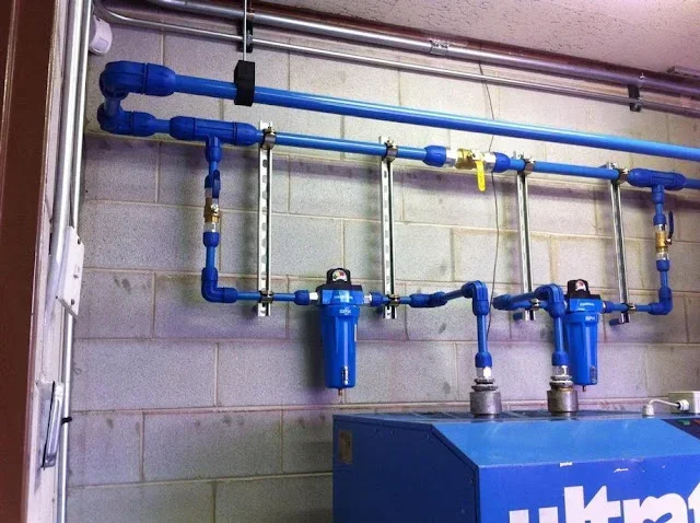
The pipes and fittings are the veins of your system. They carry compressed air from one component to the next. Common materials include copper, aluminum, steel, and polyethylene tubing. Each has its pros and cons for different applications.
Quick-connect fittings are popular in shop environments because they let you swap tools fast. Threaded fittings work well for permanent connections. Your diagram will show exactly which type goes where.
Step-by-Step Installation Guide
Now that you know the components, let us walk through the actual installation process. Following a logical sequence makes the job much easier and safer.
Step 1: Plan Your Layout
Start by sketching out your system on paper or using software. Mark where the compressor will sit, where the tank goes, and where your tools will be connected. Consider the space available and the length of piping you will need.
Keep these planning tips in mind:
- Place the compressor in a well-ventilated area.
- Keep the tank on a stable, level surface.
- Minimize the length of piping runs to reduce pressure drop.
- Position the regulator near the point of use.
- Leave room for maintenance access to all components.
For more detailed guidance on the overall setup process, check out our guide on how to set up an air compressor before you start connecting pipes.
Step 2: Gather Your Materials
Once your layout is planned, make a parts list. You will typically need piping, fittings, a pressure switch, a regulator, quick-connect couplers, Teflon tape or pipe sealant, and mounting hardware. Buy quality parts that match your system’s pressure rating.
Using under-rated fittings is a safety risk. Always check the maximum pressure rating of every component and make sure it exceeds your system’s operating pressure. When in doubt, go one size up.
Step 3: Cut and Prepare Your Piping
Measure twice and cut once. Use a pipe cutter for clean, square cuts. Deburr the inside and outside edges of each cut to prevent leaks and airflow restrictions. If you are using copper pipe, a reaming tool works great for smoothing the edges.
For shorter runs, flexible polyethylene tubing is easy to work with. It does not require soldering and can be routed around obstacles. Just make sure you use the correct diameter for your air flow needs.
Step 4: Assemble the Connections
Begin connecting the components in the order shown on your diagram. Start with the compressor to the tank connection, then add the pressure switch, and finally the output line with the regulator.
Wrap all threaded connections with Teflon tape or apply pipe sealant. Tighten fittings snugly but do not overtighten, which can crack threads or warp fittings. Use a wrench for metal fittings and hand-tighten plastic quick-connects.
For adjusting the pressure settings after assembly, our article on how to adjust the unloader valve on an air compressor provides helpful guidance for fine-tuning your system.
Step 5: Pressure Test Before Use
Never skip this step. Before you power on the system, plug all open ends and pressurize it to its maximum operating pressure. Listen for hissing sounds and check every connection with soapy water. Bubbles will reveal any leaks.
Let the system sit under pressure for at least 15 minutes. If the pressure drops, you have a leak somewhere. Mark the spot, relieve the pressure, and fix it before using the system.
Common Plumbing Mistakes and How to Avoid Them
Even experienced builders make mistakes when setting up air compressor plumbing. Knowing what goes wrong helps you avoid the same pitfalls.
Using the Wrong Pipe Size
This is the number one mistake we see. Undersized piping creates excessive pressure drop and restricts air flow to your tools. As a general rule, use the largest pipe diameter your budget and space allow. For most home shops, 1/2-inch or 3/4-inch piping works well.
Ignoring Pipe Support and Routing
Pipes need proper support to prevent stress on fittings. Unsupported pipes can sag, shift, and loosen over time. Use pipe clamps and hangers at regular intervals. Also, avoid routing pipes through areas where they could be bumped or damaged.
Forgetting the Drain Valve
Moisture collects in your tank and pipes over time. Without a drain valve, this water builds up and can cause corrosion or damage your tools. Install a drain valve at the lowest point of your system and open it regularly.
Overlooking Pressure Relief
Every compressed air system needs a pressure relief valve. This safety device releases excess pressure if the pressure switch fails. Never bypass or block a relief valve. It is there to protect you and your equipment.
Not Labeling Your Lines
As your system grows, it becomes harder to remember which line goes where. Use labeled tags or color-coded tape to mark different circuits. This simple step saves hours of confusion during troubleshooting or future modifications.
Tips for Maintaining Your Air Compressor Plumbing
Installation is only half the battle. Regular maintenance keeps your plumbing system performing at its best and extends its lifespan significantly.
Inspect Fittings Regularly
Vibration from the compressor can loosen fittings over time. Make it a habit to check all connections monthly. Tighten any that feel loose and replace any that show signs of wear or corrosion.
Drain the Tank and Lines
Moisture is the enemy of compressed air systems. Drain your tank after every use or at least once a week. If your system has longer piping runs, consider installing an air dryer or moisture separator to protect your tools.
Replace Worn Hoses and Tubing
Rubber hoses and flexible tubing degrade over time, especially in workshops with chemicals or solvents nearby. Inspect them for cracks, bulges, or soft spots. Replace any damaged sections immediately to prevent failures.
Keep Your Diagram Updated
As you modify your system, update your plumbing diagram to reflect the changes. A current diagram is invaluable when troubleshooting problems or planning future additions. It also helps if you ever need to sell the system or hire someone for repairs.
Monitor Pressure Gauges
Your pressure gauges tell you a lot about system health. If you notice the pressure dropping faster than normal, it could indicate a leak or a failing component. Check your gauges regularly and replace them if the readings seem inaccurate.
When to Call a Professional
There is no shame in calling in an expert. Some plumbing setups are simply too complex or too high-pressure for a DIY approach. Here are situations where professional help makes sense.
If you are dealing with industrial-grade compressors that operate above 200 PSI, the safety risks increase significantly. A professional installer knows the codes and regulations that apply to high-pressure systems. They also have the right tools and experience to ensure everything is up to standard.
Complex shop setups with multiple tools, branch lines, and centralized distribution benefit from professional design. A pro can optimize your layout for maximum efficiency and minimal pressure loss. They will also make sure your system meets local building codes and insurance requirements.
If you are unsure about any part of your air compressor plumbing diagram, it is always better to ask for help than to guess. A small mistake in a compressed air system can lead to serious injury or equipment damage. Trust your instincts and reach out to a qualified technician when needed.
Conclusion
Setting up an air compressor plumbing diagram does not have to be intimidating. With the right knowledge and a little patience, you can build a safe, efficient compressed air system that serves you well for years. Start with a clear diagram, choose quality parts, follow each step carefully, and never skip the pressure test.
Remember that maintenance is just as important as installation. Regular inspections, draining, and fitting checks will keep everything running smoothly. And when in doubt, do not hesitate to bring in a professional.
Now that you have the knowledge and confidence, it is time to plan your setup. Grab a pencil, sketch out your layout, and start building the compressed air system you have always wanted. Your tools and your workflow will thank you.
Frequently Asked Questions
What does an air compressor plumbing diagram show?
An air compressor plumbing diagram shows how all the components in a compressed air system connect together. It maps out the pipes, fittings, valves, tank, compressor, and regulator using standard symbols. The diagram helps you plan, install, and troubleshoot your system with confidence.
Do I need a plumbing diagram for a simple home setup?
Even for a simple setup, a diagram is very helpful. It ensures you use the right parts and connect everything in the correct order. A basic sketch on paper works just as well as a professional drawing. The key is to have a visual plan before you start cutting or fitting pipes.
What materials work best for air compressor plumbing?
Copper, aluminum, steel, and polyethylene tubing are all common choices. Copper is durable and resists corrosion. Polyethylene is flexible and easy to install. Steel handles high pressure well. Choose a material that matches your system’s pressure rating and your workshop environment.
How do I know if my plumbing setup has a leak?
The soapy water test is the easiest way to find leaks. Pressurize your system and brush soapy water on all connections. Bubbles forming at any point indicate a leak. You can also listen for hissing sounds or watch your pressure gauge for unexplained drops.
Can I modify my air compressor plumbing after installation?
Yes, you can modify your system as your needs change. Just make sure to relieve all pressure before making any changes. Update your plumbing diagram to reflect any new connections or components. If you are unsure, consult a professional before modifying high-pressure lines.
How often should I inspect my air compressor plumbing?
A monthly inspection is a good rule of thumb for most setups. Check all fittings, look for leaks, inspect hoses for wear, and drain the tank. More frequent checks may be needed in dusty or humid environments. Keeping up with regular maintenance prevents small problems from becoming big ones.