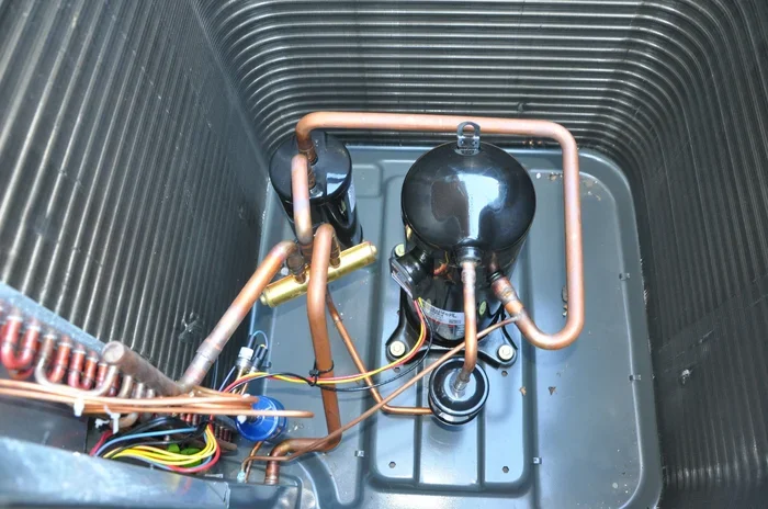
Natural Gas Compressor Diagram Guide for Beginners
A natural gas compressor diagram is a visual blueprint that shows how gas compression systems work. This guide breaks down every component, symbol, and flow path so beginners can read diagrams with confidence. You will learn what each part does, how to interpret common diagrams, and avoid costly mistakes when working with compressor systems.
A natural gas compressor diagram might look like a tangle of lines, arrows, and boxes at first glance. But once you understand the basics, these diagrams become one of the most useful tools you can have. Whether you are a homeowner checking your setup or a technician learning the ropes, knowing how to read a natural gas compressor diagram saves time, money, and headaches.
In this guide, we walk you through everything step by step. We explain what each symbol means, how gas flows through the system, and what to look for when something goes wrong. By the end, you will feel confident reading and using compressor diagrams in real-world situations. Let us get started.
Key Takeaways
- Understanding the diagram helps you troubleshoot compressor issues faster and more accurately.
- Key components include the suction valve, discharge valve, piston, cylinder, and intercooler.
- There are three main types of compressor diagrams: schematic, piping, and process flow diagrams.
- Reading a diagram step by step prevents confusion and improves safety around gas equipment.
- Common problems like pressure drops and overheating are clearly visible on a well-labeled diagram.
- Regular maintenance based on diagram insights extends compressor lifespan significantly.
📑 Table of Contents
- What Is a Natural Gas Compressor Diagram?
- Key Components Shown in a Natural Gas Compressor Diagram
- Types of Natural Gas Compressor Diagrams
- How to Read a Natural Gas Compressor Diagram Step by Step
- Common Issues Visible on a Natural Gas Compressor Diagram
- Maintenance Tips Based on Your Compressor Diagram
- How a Natural Gas Compressor Diagram Helps with Efficiency
- Common Mistakes Beginners Make When Reading Compressor Diagrams
- Final Thoughts on Natural Gas Compressor Diagrams
- Frequently Asked Questions
What Is a Natural Gas Compressor Diagram?
A natural gas compressor diagram is a drawing that represents the parts and flow paths of a gas compression system. Think of it like a map. Just as a map shows roads and landmarks, a compressor diagram shows pipes, valves, and mechanical parts. The diagram tells you how gas moves from one point to another and what happens along the way.
These diagrams come in different levels of detail. Some are simple and show only the main components. Others are highly detailed and include every fitting, gauge, and sensor. The type of diagram you use depends on what you need. A homeowner might only need a basic overview, while a technician working on a compressor station needs full technical drawings.
Why Diagrams Matter for Gas Compression Systems
Gas compression systems handle high pressures and volatile materials. Without a clear diagram, even experienced workers can make mistakes. A natural gas compressor diagram helps you understand the system before you touch any equipment. It shows where pressure builds up, where gas cools down, and where safety valves sit.
Here is why diagrams are essential:
- Safety: Knowing where high-pressure zones are keeps you safe.
- Troubleshooting: A diagram helps you trace problems quickly.
- Maintenance: You can plan routine checks based on what the diagram shows.
- Installation: New technicians use diagrams to understand system layout.
When you take a moment to study the diagram first, you avoid costly errors. This is true whether you are dealing with a small reciprocating compressor or a large industrial unit.
Key Components Shown in a Natural Gas Compressor Diagram
Every natural gas compressor diagram includes certain core components. These parts work together to compress gas and move it through the system. Let us break down each one so you can recognize them on any diagram.
Suction and Discharge Valves
The suction valve lets gas enter the compressor cylinder. The discharge valve pushes compressed gas out. These two valves control the flow direction. On a diagram, they usually appear as small triangles or arrows near the cylinder. If either valve fails, the compressor loses efficiency. You can often spot valve problems by looking at pressure readings shown on the diagram.
Piston and Cylinder Assembly
The piston moves up and down inside the cylinder. This motion compresses the gas. In a reciprocating compressor, the piston is driven by a crankshaft. The diagram shows the cylinder as a rectangular or circular shape with connecting lines to the piston rod. Understanding this relationship helps you follow how gas moves through each stage of compression.
Intercooler and Aftercooler
When gas gets compressed, it heats up. The intercooler cools the gas between compression stages. The aftercooler cools the gas after the final stage. On a diagram, these look like small boxes or heat exchangers connected by pipes. They play a big role in keeping the system efficient and safe. Without proper cooling, the compressor can overheat and fail.
Pressure Gauges and Sensors
A good diagram includes pressure gauges at key points. These show suction pressure and discharge pressure. Some diagrams also include temperature sensors and flow meters. These readings help operators know if the system is working correctly. If a gauge shows abnormal pressure, it is a clear sign something needs attention.
Types of Natural Gas Compressor Diagrams
Not all compressor diagrams look the same. Different types serve different purposes. Here are the three most common types you will encounter.
Schematic Diagrams
A schematic diagram uses simplified symbols to represent components. It does not show exact physical locations. Instead, it focuses on how the system works logically. This type is great for learning how gas flows through the compressor. If you are just starting out, the schematic diagram is the best place to begin.
Piping and Instrumentation Diagrams (P&ID)
P&ID diagrams are more detailed. They show every pipe, valve, instrument, and control point. These diagrams are used by engineers and technicians for installation and maintenance. A natural gas compressor diagram in P&ID form includes tags, line numbers, and instrument codes. While they look complex, each symbol has a specific meaning that you can learn over time.
Process Flow Diagrams
Process flow diagrams show the big picture. They focus on the overall flow of gas from inlet to outlet. These diagrams skip small details and highlight major equipment. They are helpful for understanding how the compressor fits into a larger system. For example, a process flow diagram might show how the compressor connects to a gas pipeline or storage tank.
How to Read a Natural Gas Compressor Diagram Step by Step
Reading a diagram for the first time can feel overwhelming. But if you follow a simple process, it becomes much easier. Here is a step-by-step approach that works every time.
Step 1: Identify the Legend or Key
Every diagram includes a legend. The legend explains what each symbol means. Before you read anything else, find the legend and spend a few minutes with it. Look for symbols representing valves, pipes, gauges, and compressors. Once you know the symbols, the rest of the diagram starts to make sense.
Step 2: Trace the Gas Flow Path
Start at the inlet, where raw gas enters the system. Follow the arrows along the pipes. Watch for branches where gas splits or merges. This tracing exercise helps you understand the full journey of the gas. You will see where compression happens, where cooling occurs, and where the gas exits.
Step 3: Note the Pressure and Temperature Points
Look at the gauges and sensors marked on the diagram. Write down the expected pressure and temperature at each point. Compare these numbers to what you see in real life. If there is a big difference, that tells you something may be wrong with the system.
Step 4: Check for Safety Devices
Safety devices like relief valves and emergency shutoffs appear on the diagram. Make sure you know where they are located. In an emergency, you need to act fast, and knowing the layout beforehand is critical.
Quick Tips for Beginners
- Start simple: Focus on the main flow path before diving into details.
- Use a pencil: Mark up a printed copy to trace lines and label parts.
- Ask questions: If a symbol confuses you, look it up or ask a senior technician.
- Practice regularly: The more diagrams you read, the faster you will improve.
Once you get comfortable with these steps, reading any natural gas compressor diagram becomes second nature. You can also check out our guide on how to set up an air compressor for additional context on compressor systems.
Common Issues Visible on a Natural Gas Compressor Diagram
One of the biggest benefits of understanding compressor diagrams is the ability to spot problems early. A well-labeled diagram highlights potential trouble points. Here are the most common issues you might see.
Pressure Drops Across Components
If the diagram shows a sudden drop in pressure between two points, something is blocking the flow. This could be a clogged filter, a partially closed valve, or a leak in the pipe. Pressure drops reduce efficiency and waste energy. On the diagram, these drops appear as a downward slope on the pressure line between components.
Overheating at the Discharge Side
High temperatures at the discharge point often mean the compressor is working too hard. This could result from a worn piston, a faulty intercooler, or incorrect pressure settings. The diagram will show temperature sensors or heat indicators near the discharge valve. If those readings are higher than normal, you have a problem to investigate.
Valve Failures
Valves that do not open or close properly show up clearly on a diagram. You might see gas flowing in the wrong direction or bypassing a stage entirely. Valve failures are one of the most common reasons compressors lose efficiency. Replacing a faulty valve early prevents more serious damage to the piston and cylinder.
Leak Points in the Piping
Natural gas leaks are dangerous and expensive. A diagram helps you identify every joint, weld, and connection point where a leak could occur. Regular inspection of these points based on the diagram keeps your system safe. If you suspect a leak, always follow proper safety protocols before investigating.
When to Call a Professional
Some issues go beyond what a diagram alone can solve. If you notice persistent pressure problems, unusual noises, or visible damage, call a qualified technician. You can also learn more about testing compressor windings to understand electrical issues that may affect your system. Sometimes the problem is not mechanical but electrical, and a diagram helps you narrow down the cause.
Maintenance Tips Based on Your Compressor Diagram
A natural gas compressor diagram is not just for troubleshooting. It is also a powerful tool for planning maintenance. Here is how to use it effectively.
Create a Maintenance Schedule Based on the Diagram
Look at every component on the diagram and assign a maintenance task. Valves need periodic inspection. Filters require regular replacement. Coolers should be cleaned to prevent buildup. By mapping these tasks to the diagram, you create a clear and organized maintenance plan.
Monitor Key Performance Indicators
The gauges and sensors on your diagram show you what to monitor. Track suction pressure, discharge pressure, and temperature readings regularly. If any number drifts outside the normal range, investigate immediately. Catching small changes early prevents big breakdowns later.
Keep Your Diagram Updated
Whenever you make a repair or add a new component, update the diagram. An outdated diagram leads to confusion and mistakes. Keep both physical and digital copies so you always have access to the latest version. This is especially important for larger systems with multiple stages of compression.
Use the Diagram for Training
If you train new team members, the diagram is an excellent teaching tool. Walk them through each component and explain its role. Show them where the pressure points are and how gas flows through the system. A well-trained team makes fewer mistakes and responds faster to problems.
For those wondering about sizing their equipment, our guide on how big of a compressor do I need provides helpful sizing insights that complement your diagram knowledge.
How a Natural Gas Compressor Diagram Helps with Efficiency
Efficiency is the goal of every compressor system. A well-maintained compressor uses less energy and delivers more output. The diagram plays a key role in achieving this.
By studying the flow paths and pressure points on your diagram, you can identify inefficiencies. Maybe a pipe is too long and causes friction loss. Maybe a valve is undersized and restricts flow. These issues are visible on the diagram before they become costly problems. Addressing them early saves energy and reduces operating costs.
You should also pay attention to the cooling stages shown on the diagram. Proper intercooling and aftercooling keep the gas at the right temperature before it moves to the next stage. This reduces the work the compressor has to do and extends the life of internal components like the piston and cylinder walls.
Another way to boost efficiency is to ensure all connections shown on the diagram are tight and leak-free. Even a small leak wastes gas and lowers system performance. Regular visual inspections of every joint and fitting referenced in the diagram go a long way toward maintaining peak efficiency.
Understanding your natural gas compressor diagram also helps when choosing replacement parts. If a valve or sensor fails, the diagram tells you the exact model and location. This prevents guesswork and ensures you install the right component the first time.
Common Mistakes Beginners Make When Reading Compressor Diagrams
Everyone makes mistakes when learning something new. Here are the most common errors beginners make with compressor diagrams and how to avoid them.
- Skipping the legend: Without understanding the symbols, the diagram is just lines and shapes. Always start with the legend.
- Ignoring flow direction: Arrows on the diagram show the direction of gas flow. Reading against the flow leads to confusion.
- Overlooking scale: Some diagrams are not drawn to scale. Do not assume physical sizes based on how components appear on paper.
- Mixing diagram types: A schematic diagram and a P&ID look very different. Do not compare them directly without understanding their purpose.
- Forgetting to update: A diagram that does not match the actual system is worse than no diagram at all. Keep it current.
Avoiding these mistakes puts you ahead of most beginners. Take your time, be patient, and let the diagram guide you through the system.
Final Thoughts on Natural Gas Compressor Diagrams
A natural gas compressor diagram is more than just a technical drawing. It is a roadmap that helps you understand, operate, and maintain a complex gas compression system. Whether you are a beginner or an experienced technician, spending time with these diagrams pays off in safety, efficiency, and confidence.
Start with the basics. Learn the symbols. Trace the flow paths. Note the pressure and temperature points. As your understanding grows, you will find that diagrams become an indispensable part of your toolkit. They help you troubleshoot faster, plan maintenance better, and avoid costly mistakes.
Remember, every expert was once a beginner. The fact that you are reading this guide shows you are on the right track. Keep practicing, keep asking questions, and never stop learning. The world of gas compression is fascinating, and a solid understanding of the diagram is your first step toward mastering it.
For more information on related topics, explore our article on how to choose an air compressor to understand the broader landscape of compressor selection and application.
Frequently Asked Questions
What does a natural gas compressor diagram show?
A natural gas compressor diagram shows all the major components of a compression system, including valves, pistons, cylinders, coolers, and pipes. It also shows how gas flows through the system and where pressure and temperature changes occur. The diagram helps you understand the complete path of gas from inlet to outlet.
Are there different types of compressor diagrams?
Yes, there are three main types: schematic diagrams, piping and instrumentation diagrams (P&ID), and process flow diagrams. Schematic diagrams use simplified symbols to show how the system works logically. P&ID diagrams are highly detailed and include every pipe and instrument. Process flow diagrams show the big picture of gas movement through the system.
How can I tell if my compressor has a problem using the diagram?
Look for pressure drops, temperature spikes, or unusual flow patterns on the diagram. If a gauge shows a reading that is significantly higher or lower than expected, that is a warning sign. The diagram helps you trace the problem back to a specific component, such as a faulty valve or a clogged filter.
Do I need technical training to read a compressor diagram?
Basic training helps, but anyone can learn to read a compressor diagram with practice. Start by studying the legend and understanding what each symbol represents. Then trace the gas flow path from start to finish. Over time, you will become more comfortable and confident reading even complex diagrams.
How often should I refer to my compressor diagram?
You should refer to the diagram whenever you perform maintenance, troubleshoot a problem, or make a repair. It is also a good idea to review the diagram during routine inspections. Keeping the diagram updated and accessible ensures you always have accurate information at hand.
Can I use a natural gas compressor diagram for troubleshooting electrical issues?
Yes, a diagram can help you identify electrical components like sensors, control panels, and motors within the system. However, for detailed electrical troubleshooting, you may need a separate electrical schematic. The compressor diagram gives you a solid starting point for narrowing down where the problem lies.