Air Compressor Pressure Switch Diagram and How It Works
An air compressor pressure switch diagram shows you exactly how the switch controls your compressor’s motor by monitoring tank pressure. This guide breaks down every wire, terminal, and connection so you can read, understand, and even troubleshoot your setup with confidence. Whether you are a DIYer or a seasoned mechanic, knowing this diagram saves time, money, and guesswork.
Have you ever wondered what makes your air compressor start and stop at just the right moments? The answer lies in a small but mighty component called the pressure switch. It acts as the brain of your compressor, telling the motor when to kick on and when to shut off based on the air pressure inside the tank. Without it, your compressor would either run nonstop or never start at all.
In this guide, we will walk you through the air compressor pressure switch diagram in plain, simple language. You will learn what each part does, how to read the wiring connections, and how to troubleshoot common problems. We will also share practical tips that help you get the most out of your compressor every single day.
Whether you are setting up a new compressor, replacing an old switch, or just curious about how things work, this article has you covered. Let us dive right in and make sense of this essential component.
Key Takeaways
- Pressure Switch Basics: The switch turns your compressor motor on and off based on tank pressure levels, protecting your system from damage.
- Wiring Matters: Understanding the wiring diagram ensures safe and correct electrical connections every time.
- Adjustment Is Key: Knowing how to adjust cut-in and cut-out pressure extends compressor life and improves efficiency.
- Troubleshooting Is Easy: Most pressure switch problems stem from simple issues like loose wiring or a stuck diaphragm.
- Safety First: Always disconnect power before working on any part of your compressor’s electrical system.
📑 Table of Contents
- What Is an Air Compressor Pressure Switch?
- Reading the Air Compressor Pressure Switch Diagram
- How the Pressure Switch Works Step by Step
- How to Adjust Your Pressure Switch
- Common Pressure Switch Problems and How to Fix Them
- Safety Tips for Working with Pressure Switch Wiring
- Understanding the Internal Components of the Switch
- Pressure Switch Diagrams for Different Compressor Types
- Final Thoughts
What Is an Air Compressor Pressure Switch?
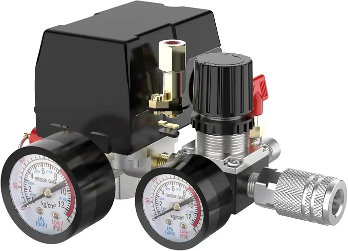
The pressure switch is a small device mounted on your compressor tank or near the pump. Its job is simple but critical. It monitors the air pressure inside the tank and sends an electrical signal to the motor. When pressure drops to a certain level, the switch tells the motor to start. When pressure reaches the top limit, it tells the motor to stop.
Think of it like a thermostat in your home. Just as a thermostat turns your heater on when the room gets cold, the pressure switch turns your compressor on when the tank gets low. It keeps everything running smoothly and safely.
Most pressure switches have two main settings. The first is the cut-in pressure. This is the lower limit where the motor starts. The second is the cut-out pressure. This is the higher limit where the motor stops. The difference between these two numbers is called the pressure differential. Understanding these three values is the first step to reading any pressure switch diagram.
Why the Pressure Switch Matters
Your compressor tank holds a finite amount of air. Without a pressure switch, the motor would run continuously, overheating and burning out quickly. The switch protects your investment by cycling the motor on and off as needed. This also saves energy and reduces wear on the compressor pump.
A good pressure switch also prevents dangerous over-pressurization. If the tank pressure gets too high, the switch cuts power to the motor. This works hand in hand with the pressure relief valve to keep your system safe.
Reading the Air Compressor Pressure Switch Diagram
When you first look at a pressure switch diagram, it can feel overwhelming. There are wires, terminals, symbols, and arrows everywhere. But once you break it down, it becomes much simpler. Let us go through the main parts of the diagram step by step.
Understanding the Terminals
Most pressure switches have three or four terminals on the back. These are the connection points where wires attach. The most common setup includes:
- Terminal L1 (Line): This is the power input. It connects directly to your electrical supply.
- Terminal L2 (Load): This is the power output. It sends electricity to the motor contactor or starter.
- Terminal 1 and Terminal 2: These are the switch contacts. They open and close based on pressure changes.
In a basic pressure switch diagram, you will see a line coming from the power source to the Line terminal. From there, the current flows through the switch contacts to the Load terminal. When the switch is closed (pressure is low), electricity flows freely. When the switch is open (pressure is high), the circuit breaks and the motor stops.
The Wiring Path Explained
Here is how the wiring path typically works in a standard setup. Power enters the switch at the Line terminal. It then passes through the internal contacts of the switch. These contacts are what physically open and close based on pressure. Finally, the power exits through the Load terminal and heads to the motor starter.
Some diagrams also show a connection to a pressure gauge or a pressure sensor. These provide visual feedback so you can see the current tank pressure at a glance. They are not part of the main electrical circuit but are helpful for monitoring.
If you are also working with generator setups or transfer switches, the wiring principles share similarities with how to wire a generator transfer switch, as both involve managing power flow through controlled switching mechanisms.
How the Pressure Switch Works Step by Step
Now that you have seen the diagram, let us walk through the actual operation. Understanding the process helps you troubleshoot problems faster and makes maintenance much easier.
Step 1: Starting the Compressor
When you turn on your compressor, the tank is at or near zero pressure. The pressure switch detects this low pressure and closes its internal contacts. This completes the electrical circuit, sending power to the motor. The motor starts running and begins pumping air into the tank.
At this point, the switch is in the closed position. Think of it like a door that is open, letting electricity flow through.
Step 2: Building Pressure
As the compressor pump works, air builds up inside the tank. The pressure gauge on your compressor shows the rising numbers. The pressure switch monitors this increase constantly through a diaphragm or a lever mechanism inside the switch body.
The pump keeps running until the pressure reaches the cut-out setting. At that point, the internal mechanism in the switch pushes the contacts apart. The circuit breaks, and the motor shuts off.
Step 3: Using Air and the Cycle Repeats
When you use compressed air from the tank, the pressure begins to drop. Once it falls to the cut-in pressure, the switch contacts close again. The motor starts up and the cycle begins once more. This on-and-off cycling happens automatically and keeps your air supply steady.
Most home and shop compressors have a pressure differential of about 20 to 40 PSI. For example, a switch might turn the motor on at 100 PSI and off at 130 PSI. That 30 PSI difference is the pressure differential. Adjusting this range is possible on many models, which we will cover next.
How to Adjust Your Pressure Switch
Adjusting the pressure switch allows you to control when your compressor starts and stops. This is useful if you need a different pressure range for your tools or if the factory settings do not match your setup. Most switches have two adjustment screws or knobs.
The Cut-In Adjustment
The cut-in screw controls the lower pressure limit. When you turn this screw clockwise, the cut-in pressure increases. That means the motor will start at a higher tank pressure. Turning it counterclockwise lowers the cut-in pressure.
Always make small adjustments. Turn the screw a quarter turn at a time and then test the system. Large changes can cause the compressor to short-cycle, which means it starts and stops too frequently. Short cycling damages the motor over time.
The Cut-Out Adjustment
The cut-out screw controls the upper pressure limit. Clockwise turns increase the cut-out pressure, and counterclockwise turns decrease it. The relationship between the cut-in and cut-out settings determines your pressure differential.
Here is a quick tip. Many compressors come with a pre-set pressure range stamped on the switch body. Common ranges include 100 to 130 PSI, 110 to 145 PSI, and 125 to 175 PSI. If you are unsure of your settings, check this stamp first before making any adjustments.
Quick Tips for Adjustment
- Always adjust the switch with the compressor off and unplugged.
- Use a reliable pressure gauge to verify your settings.
- Never exceed the maximum pressure rating listed on the tank.
- Make only one adjustment at a time and test before making another.
- Keep a log of your settings so you can return to them if needed.
Common Pressure Switch Problems and How to Fix Them
Pressure switches are reliable, but they can develop problems over time. Here are the most common issues and what you can do about them.
Compressor Does Not Start
If your compressor will not start, the first thing to check is the pressure switch. The contacts inside may be stuck open. This can happen from corrosion, dust buildup, or a worn-out spring. Open the switch housing and inspect the contacts. Clean them with fine-grit sandpaper if they look corroded. If the spring is weak or broken, replace the switch entirely.
Also check the wiring at the terminals. Loose or corroded connections are a very common cause of no-start problems. A simple tightening or cleaning often fixes this.
Compressor Runs Continuously
A compressor that never shuts off usually has a switch that is stuck closed. The contacts may be welded together from arcing, or the diaphragm inside may be torn. In this case, the switch cannot detect the rising pressure and keeps sending power to the motor.
This is a serious problem. A continuously running compressor can overheat, trip breakers, or even cause tank failure. Turn off the compressor immediately and replace the pressure switch.
Short Cycling
Short cycling means the compressor turns on and off too quickly, often in just a few seconds. This usually happens when the pressure differential is set too narrow. The tank reaches the cut-out pressure almost immediately after the cut-in pressure.
To fix this, widen the pressure differential by adjusting the cut-out screw upward or the cut-in screw downward. This gives the pump more time to build pressure and reduces wear on the motor.
Pressure Switch Leaks Air
Sometimes you will hear a hissing sound near the switch. This usually means the diaphragm or the housing seal is damaged. Air leaks from the tank through the switch body instead of staying contained.
A leaking pressure switch should be replaced promptly. Continuing to use it wastes compressed air and puts extra strain on the pump.
Safety Tips for Working with Pressure Switch Wiring
Working with electricity and compressed air requires respect and caution. Follow these safety tips every time you handle your pressure switch or its wiring.
- Always disconnect power at the breaker before touching any wires or opening the switch housing.
- Use a voltage tester to confirm the power is off before you begin any work.
- Wear safety glasses when working near the compressor tank or pump area.
- Never bypass the pressure switch. Running the compressor without a functioning switch is extremely dangerous.
- Check the pressure relief valve regularly. It works alongside the switch to prevent over-pressurization.
- Keep the area dry. Water and electricity do not mix, so keep your compressor and switch in a dry location.
Proper wiring and safe handling of the pressure switch also apply to other compressed air systems. For instance, the electrical safety principles you learn here carry over when setting up larger systems, much like the careful wiring needed for a generator transfer switch installation where precision and safety are equally critical.
Understanding the Internal Components of the Switch
To truly understand the pressure switch diagram, it helps to know what is inside the housing. Most pressure switches contain a few key components that work together to control the circuit.
The diaphragm is a flexible rubber or silicone membrane that moves in response to air pressure. When tank pressure rises, the diaphragm pushes upward or inward. This movement triggers the switch mechanism. When pressure drops, the diaphragm returns to its original position.
The spring provides resistance against the diaphragm. The tension of the spring determines the pressure at which the switch activates. Adjusting the spring tension is how you change the cut-in and cut-out pressures.
The contacts are metal pieces that either touch or separate to complete or break the electrical circuit. When the diaphragm pushes against the spring and reaches the set point, the contacts separate. When pressure drops and the spring pushes back, the contacts come together again.
Some switches also include a lever or an adjustment screw that connects to the spring mechanism. This is what you turn when you want to change your pressure settings. The lever provides a mechanical advantage, making it easier to set precise pressure points.
Understanding these internal parts helps you diagnose problems faster. If your switch is not triggering at the right pressure, the spring may be weak or the contacts may be worn. Knowing the components gives you the confidence to fix issues yourself.
For more complex setups involving multiple switches or higher voltage systems, the wiring approach can get more involved. In these cases, consulting a professional or referring to detailed installation guides is always a smart move, similar to how you would follow a thorough guide for a generator transfer switch when dealing with higher electrical loads.
Pressure Switch Diagrams for Different Compressor Types
Not all compressors use the same type of pressure switch. The diagram varies depending on the compressor design and the switch style. Here is a quick look at the most common types.
| Switch Type | How It Works | Common Use |
|---|---|---|
| Diaphragm Switch | Uses a flexible membrane that moves with pressure changes | Most home and small shop compressors |
| Lever-Actuated Switch | Uses a mechanical lever connected to the tank pressure | Larger industrial compressors |
| Electronic Switch | Uses a digital sensor and electronic controls | High-precision or automated systems |
Diaphragm switches are the most common in home workshops. They are simple, reliable, and easy to adjust. Lever-actuated switches handle higher pressures and are found in industrial settings. Electronic switches offer the most precision and often include digital displays and programmable settings.
No matter which type you have, the basic principle remains the same. The switch monitors tank pressure and controls the motor circuit accordingly. The diagram may look different, but the function is identical across all types.
Final Thoughts
The air compressor pressure switch diagram is your roadmap to understanding one of the most important parts of your compressor. Once you know how to read it, you can troubleshoot problems, make adjustments, and keep your compressor running at peak performance.
Remember that the pressure switch protects both your compressor and yourself. It prevents over-pressurization, reduces motor wear, and ensures efficient operation. Taking the time to understand its diagram and function pays off every time you use your compressor.
Keep your switch clean, check the wiring connections periodically, and never ignore warning signs like strange noises or leaking air. A well-maintained pressure switch gives you years of reliable service. And with the knowledge you have gained from this guide, you are now equipped to handle most pressure switch challenges with confidence.
Your compressor is a valuable tool. Treat the pressure switch with care, and it will take care of you in return. Happy compressing!
Frequently Asked Questions
What does a pressure switch diagram show?
A pressure switch diagram shows the electrical connections between the switch, the power supply, and the motor. It maps out which wires connect to which terminals and how the switch controls the circuit based on tank pressure.
Can I adjust the pressure settings on my compressor switch?
Yes, most pressure switches have adjustment screws for the cut-in and cut-out pressures. Turn them carefully in small increments and always test the settings after adjusting.
Why does my compressor pressure switch keep tripping?
A switch that keeps tripping could be caused by a narrow pressure differential, a faulty diaphragm, or loose wiring. Check the adjustment settings first, then inspect the switch internals and connections.
Is it safe to work on the pressure switch wiring myself?
It is safe as long as you disconnect power at the breaker before starting any work. Always use a voltage tester to confirm the power is off and follow proper safety procedures.
What is the difference between cut-in and cut-out pressure?
Cut-in pressure is the lower limit where the motor starts. Cut-out pressure is the upper limit where the motor stops. The difference between the two is called the pressure differential.
How often should I inspect my pressure switch?
Inspect your pressure switch at least once every few months. Check for loose wires, corrosion on terminals, and any signs of air leaks around the switch housing.