Compressor Capacitor Wiring Diagram A Step by Step Guide
A compressor capacitor wiring diagram shows you exactly how to connect the capacitor to your compressor motor safely. Whether you are dealing with a single phase compressor or a dual run capacitor, this step by step guide walks you through every connection point. You will learn to identify terminals, understand wiring colors, and avoid common mistakes that cause compressor failure.
A compressor capacitor wiring diagram is one of the most important tools you need when working on any compressor system. Whether you are replacing a bad capacitor or troubleshooting a compressor that will not start, knowing how to read and follow the wiring diagram makes all the difference. This guide breaks everything down into simple steps that anyone can follow.
Compressors use capacitors to give the motor that extra burst of energy it needs to start and keep running. Without a properly wired capacitor, your compressor will struggle, overheat, or fail to start altogether. That is why understanding your compressor capacitor wiring diagram is so important for both DIY enthusiasts and professionals.
In this article, we will walk you through every step of reading, understanding, and following a compressor capacitor wiring diagram. You will learn about the different types of capacitors, what each terminal does, and how to make safe electrical connections. By the end, you will feel confident tackling this job on your own.
Key Takeaways
- Know Your Capacitor: Understanding the difference between start and run capacitors is essential before you begin any wiring.
- Follow the Diagram: A compressor capacitor wiring diagram prevents costly errors and keeps your system running safely.
- Safety First: Always disconnect power and discharge the capacitor before touching any wires or terminals.
- Check Your Ratings: Matching the correct capacitor rating to your compressor motor ensures optimal performance.
- Test After Wiring: Always verify your connections with a multimeter before powering the compressor back on.
- Replace When Needed: A failing capacitor causes hard starting, overheating, and compressor clutch issues.
- Keep It Simple: Most compressor capacitor wiring follows a clear pattern once you understand the terminal labels.
📑 Table of Contents
Understanding the Compressor Capacitor
Before you look at any wiring diagram, you need to understand what a compressor capacitor does and why it matters. The capacitor stores electrical energy and releases it quickly to help the compressor motor start and run smoothly. Think of it like a small battery that gives your compressor the boost it needs.
There are two main types of capacitors you will find in compressor systems. A start capacitor gives the motor extra torque when it first kicks on. A run capacitor helps the motor maintain steady speed while it runs. Some systems use a single capacitor that handles both jobs, which is called a dual run capacitor.
Start vs Run Capacitor
The start capacitor has a higher capacitance rating, usually measured in microfarads (uF). It only works for a brief moment during startup. Once the motor reaches a certain speed, a centrifugal switch disconnects it from the circuit. The run capacitor stays connected the entire time the compressor is running. It keeps the motor working efficiently.
When you look at a compressor capacitor wiring diagram, the first thing you will notice is how the terminals are labeled. Most capacitors have three terminals marked C, FAN, and COMP. The C stands for common, FAN connects to the fan motor, and COMP connects to the compressor motor. Understanding these labels is the key to wiring your capacitor correctly.
Reading the Compressor Capacitor Wiring Diagram
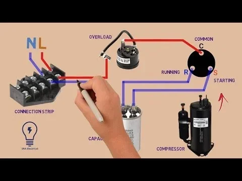
A compressor capacitor wiring diagram might look complicated at first glance, but it is actually quite straightforward once you know what to look for. The diagram shows you the electrical path from the power source through the capacitor and into the compressor motor. Each line represents a wire, and each symbol represents a component.
You will see lines coming from the power supply, lines going to the compressor motor, and lines connecting to the run capacitor. The diagram also shows where the relay or contactor fits into the circuit. Once you understand what each symbol means, the whole picture comes together.
Key Symbols to Know
Here are the most common symbols you will see on a compressor capacitor wiring diagram:
- Lines: Represent wires carrying electrical current between components.
- Circles with letters: Represent terminals on the capacitor or motor.
- Squares or rectangles: Represent relays, contactors, or overload protectors.
- Zigzag lines: Represent resistors or potential relay coils.
- Ground symbols: Show where the safety ground wire connects.
When you study your diagram, trace the path with your finger from the power source to the capacitor and then to the motor. This simple exercise helps you understand the flow of electricity and makes the wiring process much easier.
Tools You Need for the Job
Before you start working on your compressor capacitor wiring diagram connections, gather the right tools. Having everything ready saves time and keeps you safe throughout the process.
- Multimeter: You need this to test voltage, continuity, and capacitor charge.
- Screwdrivers: Both flathead and Phillips head for terminal connections.
- Wire strippers: To prep wire ends for clean connections.
- Voltage tester: To confirm power is off before you touch anything.
- Wire nuts or crimp connectors: For secure wire connections.
- Electrical tape: To insulate connections and prevent shorts.
- Work gloves and safety glasses: Essential protection when working with electricity.
You should also have your compressor capacitor wiring diagram printed out or visible on a screen nearby. This way you can refer to it as you work and make sure every connection matches the diagram exactly.
Step by Step Wiring Process
Now that you understand the diagram and have your tools ready, it is time to start wiring. Follow these steps carefully and never rush the process.
Step 1: Disconnect Power
The first and most important step is to disconnect all power to the compressor. Turn off the breaker or unplug the unit. Use your voltage tester to confirm there is no power reaching the compressor. Never assume the power is off always verify it.
Step 2: Discharge the Capacitor
Capacitors can hold a dangerous electrical charge even when the power is off. Use an insulated screwdriver to discharge the capacitor by shorting the terminals together. Wear your safety gloves and glasses for this step. A charged capacitor can deliver a serious shock or even cause injury.
Step 3: Identify the Terminals
Look at your compressor capacitor wiring diagram and identify each terminal on the capacitor. The common terminal (C) connects to the shared wire between the compressor motor and fan motor. The fan terminal (FAN) connects to the fan motor winding. The compressor terminal (COMP) connects to the compressor motor winding.
Step 4: Connect the Wires
Follow the diagram and connect each wire to its correct terminal. Use wire strippers to remove a small amount of insulation from each wire end. Wrap the wire around the terminal screw and tighten it firmly. Make sure connections are snug but do not over-tighten and damage the terminal.
Step 5: Insulate All Connections
After making all connections, wrap each terminal with electrical tape. This prevents accidental contact between wires and reduces the risk of shorts. Double check every connection against the diagram before moving on.
Step 6: Test the Wiring
Before restoring power, use your multimeter to check for continuity and proper voltage at each terminal. Make sure there are no loose wires or exposed copper. Once everything looks good, restore power and listen for the compressor to start smoothly.
Common Mistakes to Avoid
Even experienced technicians make mistakes when working with a compressor capacitor wiring diagram. Here are the most common errors and how to avoid them.
- Skipping the discharge step: A charged capacitor can cause serious injury. Always discharge it before handling any wires.
- Mixing up terminals: Connecting the fan wire to the compressor terminal or vice versa will cause the compressor to malfunction.
- Using the wrong capacitor rating: Always match the microfarad and voltage ratings to what your compressor requires. Using the wrong rating can damage the motor.
- Loose connections: A loose wire creates resistance, which causes overheating and premature failure of the capacitor and motor.
- Ignoring the wiring diagram: Do not guess or rely on memory. Always follow the diagram for your specific compressor model.
- Forgetting to check the relay: If your compressor has a potential relay, make sure it is wired correctly according to the diagram.
If you ever run into issues where the compressor clutch not engaging after wiring, double check all your connections against the diagram. A single misplaced wire can prevent the clutch from receiving power.
Another common mistake is using damaged wires or frayed connections. Always inspect your wiring before starting the job and replace any compromised wires. If you need replacement parts, visit an air compressor parts store to find the right components for your system.
Troubleshooting After Wiring
After you complete the wiring, you might notice some issues during the first few starts. This is normal and usually easy to fix. Here is what to watch for and how to address common problems.
Compressor Does Not Start
If the compressor does not start after you wire the capacitor, check a few things first. Verify that all connections match the compressor capacitor wiring diagram. Use your multimeter to test the capacitor for proper capacitance. A bad capacitor will show a reading outside its rated range. If the capacitor is good, check the compressor clutch and relay for proper operation.
Compressor Hums But Does Not Start
A humming compressor usually means the start capacitor is not providing enough energy to kick the motor into motion. This could be caused by a weak capacitor, a loose wiring connection, or a failing relay. Disconnect power and test each component before replacing anything.
Compressor Trips the Breaker
If your compressor trips the breaker shortly after starting, you may have a wiring short or a capacitor with the wrong rating. Go back to the diagram and check every connection. Make sure no bare wire is touching another wire or the compressor housing.
Compressor Runs but Gets Hot
Excessive heat during operation often points to a run capacitor that is failing or wired incorrectly. A bad capacitor can cause the motor to draw too much current, which leads to overheating. If you notice this issue, turn off the compressor and inspect the capacitor and all wiring connections.
For more help diagnosing compressor issues, check out our guide on how to diagnose AC compressor problems. It covers the most common symptoms and what they mean for your system.
Safety Tips for Working with Compressor Capacitors
Working with capacitors and electrical components requires respect and caution. A compressor capacitor wiring diagram will guide your connections, but safety practices protect you from harm.
- Always disconnect power: This is non negotiable. Every single time you work on a compressor, kill the power first.
- Discharge the capacitor: Even after disconnecting power, capacitors hold a charge. Always discharge them before handling.
- Wear protective gear: Gloves and safety glasses protect you from sparks and electrical shock.
- Work in a dry area: Moisture and electricity do not mix. Keep your work area dry at all times.
- Use insulated tools: Insulated screwdrivers and handles reduce the risk of accidental shock.
- Know your limits: If you feel unsure about any step, consult a licensed technician. Electrical work can be dangerous.
Taking these precautions seriously keeps you safe and protects your compressor from damage. A properly wired capacitor will help your compressor run efficiently for years to come.
When to Replace the Capacitor
Sometimes the problem is not the wiring but the capacitor itself. Knowing when to replace your compressor capacitor can save you from costly repairs down the road. A failing capacitor often shows clear warning signs before it completely stops working.
Look for bulging or leaking on the capacitor body. A healthy capacitor should look flat and clean. If you see any swelling, cracking, or oil leaking from the casing, the capacitor needs immediate replacement. You might also notice the compressor taking longer to start or struggling to reach full speed.
Use your multimeter to test the capacitor if you suspect it is failing. Compare the reading to the rating printed on the capacitor. A reading significantly lower than the rated value means the capacitor is worn out and should be replaced. You can find replacement capacitors at any air compressor parts store or online retailer.
When replacing a capacitor, always match the exact microfarad and voltage ratings. Using a capacitor with incorrect specifications can damage your compressor motor and void your warranty. If you are unsure about the right part, refer to your compressor manual or contact the manufacturer.
For more information on capacitor-related issues, you might want to read about can a bad capacitor cause a compressor to overheat and understand the connection between failing capacitors and compressor performance.
Conclusion
A compressor capacitor wiring diagram is your best friend when working on any compressor electrical system. It gives you a clear roadmap for connecting the capacitor, motor, and power supply safely and correctly. By following the steps in this guide, you can tackle capacitor wiring with confidence and avoid the most common pitfalls.
Remember to always prioritize safety. Disconnect power, discharge the capacitor, and verify every connection before restoring electricity. Take your time, follow the diagram closely, and do not hesitate to call a professional if you feel uncertain. A properly wired capacitor keeps your compressor running smoothly and efficiently for many years.
Whether you are a seasoned DIYer or just getting started with compressor maintenance, understanding your compressor capacitor wiring diagram is a skill that pays off every time you work on your system. Keep this guide handy, follow the steps carefully, and you will have your compressor up and running in no time.
Frequently Asked Questions
What is a compressor capacitor wiring diagram?
A compressor capacitor wiring diagram is a visual map that shows how the capacitor connects to the compressor motor and other electrical components. It uses symbols and lines to represent wires, terminals, and parts. Following the diagram ensures every connection is made correctly and safely.
Can I wire a compressor capacitor without a diagram?
You can, but it is not recommended. Without a diagram, you risk connecting wires to the wrong terminals, which can damage the compressor motor or cause electrical shorts. Always use the diagram that matches your specific compressor model for the safest and most accurate results.
What happens if I wire the capacitor backwards?
Wiring a capacitor backwards usually does not cause immediate damage, but it can prevent the compressor from starting properly. The motor may hum, struggle, or fail to reach full speed. Always match the wire colors and terminal labels from your compressor capacitor wiring diagram exactly.
How do I know if my compressor capacitor is bad?
Signs of a bad capacitor include the compressor taking too long to start, humming without starting, overheating, or not running at all. You can also test the capacitor with a multimeter. If the reading is significantly lower than the rated value, the capacitor needs replacement.
Is it safe to replace a compressor capacitor myself?
Yes, it is safe as long as you follow proper safety procedures. Always disconnect power, discharge the capacitor, and use insulated tools. If you are comfortable working with basic electrical components and follow the wiring diagram carefully, capacitor replacement is a manageable DIY job.
What capacitor rating do I need for my compressor?
The correct rating is printed on the capacitor itself and in your compressor manual. Match both the microfarad (uF) and voltage ratings exactly. Using the wrong rating can cause poor performance, overheating, or motor damage. When in doubt, contact the compressor manufacturer for guidance.