Air Brake Compressor Diagram Everything You Need to Know
The air brake compressor diagram is the essential map of your truck’s entire braking system. It shows how compressed air moves from the pump through tanks and valves to the brake chambers. Understanding this diagram helps you spot problems early and keep your heavy-duty vehicle running safely.
The air brake compressor diagram is the starting point for understanding how your truck’s braking system works. Every line and symbol on that diagram tells a story about compressed air flow, pressure regulation, and safety. If you’ve ever wondered what happens when you press the brake pedal, the diagram shows the complete path.
Heavy-duty trucks, buses, and trailers rely on air brakes to stop safely. Unlike hydraulic brakes, air brakes use pressurized air to push brake shoes or pads against drums or rotors. The compressor is the machine that builds that pressure. Without it, the system has no power. That’s why reading the air brake compressor diagram is so important for drivers, mechanics, and fleet managers.
In this guide, we’ll walk you through every part of the diagram. You’ll learn what each component does, how air moves, and what to look for when something goes wrong. We’ll also share quick maintenance tips that can save you time and money. By the end, you’ll feel confident reading any air brake system diagram like a pro.
Key Takeaways
- The diagram reveals every component: You’ll see the pump, tanks, valves, and brake chambers all in one view.
- The compressor pump is the heart: It draws in air and pressurizes it for the entire air brake system.
- The governor regulates pressure: It cuts the compressor in and out to maintain safe air pressure levels.
- The unloader valve reduces load: This prevents the engine from working too hard during startup and idle.
- Air dryers and tanks prevent moisture: They keep water and oil out of the brake lines, protecting brake chambers and linings.
- Regular maintenance keeps the flow clear: Checking belts, draining tanks, and inspecting valves can prevent costly breakdowns.
📑 Table of Contents
Understanding the Air Brake Compressor Diagram
What Does the Diagram Show?
The diagram is a visual map of the entire air brake system. It shows the compressor, the governor, the air tanks, the dryer, the valves, and the brake chambers. Each part is connected by lines that represent air pipes and hoses. Arrows often show the direction of airflow. Pressure values are marked at key points.
You’ll see symbols for the compressor pump, the air dryer, the wet tank, the dry tank, the treadle valve, and the relay valve. Some diagrams also include the brake chambers and slack adjusters. The layout may vary by manufacturer, but the basic flow is always the same.
Why It Matters for Safety
A single leak or stuck valve can cause a complete brake failure. The diagram helps you trace the air path and find weak spots. When you know what normal looks like, you can spot abnormal pressure drops quickly. This knowledge can prevent accidents and costly roadside repairs.
Quick Tip: Keep a printed copy of your specific air brake compressor diagram in the cab. It’s a fast reference during pre-trip inspections and makes troubleshooting much easier.
Key Components of the Air Brake Compressor System
The Compressor Pump
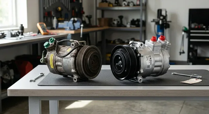
The pump is the heart of the system. It’s usually belt-driven from the engine. Inside, pistons or rotors draw in outside air and squeeze it to high pressure. The air brake compressor must deliver a steady supply of compressed air at the right pressure, typically 100 to 135 psi.
Common Types
Most heavy-duty trucks use either a piston compressor or a rotary screw compressor. Piston models are common and affordable. Rotary screw units run cooler and last longer under heavy use. Both types appear on the air brake compressor diagram with slightly different symbols.
| Feature | Piston Compressor | Rotary Screw Compressor |
|---|---|---|
| Common Use | Medium-duty trucks | Heavy-duty, high-mileage trucks |
| Maintenance | More moving parts, valve checks | Fewer valves, longer intervals |
| Noise Level | Louder | Quieter |
| Cost | Lower initial cost | Higher initial cost |
The Unloader Valve
When the engine starts, the compressor needs to run without building pressure right away. The unloader valve does this. It holds the compressor’s outlet open so air can flow freely. Once the system reaches cut-in pressure, the valve closes and the pump begins building air pressure.
Expert Insight: A stuck unloader valve is a common problem. If it stays open, the compressor never builds enough pressure. If it stays closed, the engine works too hard during startup. Check the unloader valve early when diagnosing pressure loss.
The Governor
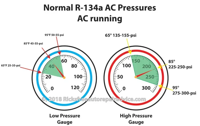
The governor is the system’s brain. It monitors air pressure and tells the compressor when to cut in and cut out. When pressure drops to the cut-in level (usually around 60 psi), the governor engages the compressor clutch. When pressure reaches the cut-out level (around 135 psi), it disengages the clutch.
Quick Tip: Listen for the compressor clutch engaging and disengaging. If you don’t hear it, the governor may be faulty or the electrical connection is loose.
Air Tanks and Dryers
The system stores compressed air in tanks. The wet tank sits near the compressor and collects oil and moisture. A air dryer then removes water vapor before air reaches the dry tanks and brake valves. Desiccant or membrane dryers are common. They prevent freeze-ups in cold weather and corrosion in brake lines.
Common Mistake: Many drivers forget to drain the wet tank manually if it lacks an automatic drain. Moisture can corrode tank walls and freeze in valves during winter.
Brake Valves and Chambers
The brake valve (treadle valve) is what you press with your foot. It meters air to the brake chambers. Each wheel has a chamber that pushes a slack adjuster, which applies the brake lining to a drum or rotor. The relay valve helps apply brakes faster by feeding air directly to the chambers.
How the Air Brake System Operates
The Compression Cycle
The compression cycle begins when the engine runs the compressor. Air enters through an intake filter. The pump compresses it and sends it to the wet tank. The governor controls the cycle. When pressure is low, the compressor engages. When pressure is high, it unloads and stops building.
Air Storage and Distribution
Compressed air moves from the wet tank to the air dryer. The dryer removes moisture. Then the air flows to the dry tanks, which act as reserves. From the dry tanks, air travels to the brake valve, relay valve, and other control valves. Each branch supplies air to specific brake chambers.
Brake Application Sequence
When you press the brake pedal, the treadle valve opens. This allows stored air to flow into the brake chambers. The air pushes a piston, which turns a slack adjuster. The slack adjuster moves the brake cam, forcing the shoes against the drum. The brake application happens quickly and firmly. When you release the pedal, the quick release valve vents the air from the chambers, and the brakes release.
Common Mistake: Many drivers forget to check the slack adjusters. If they are out of adjustment, the brakes won’t apply fully, even if the air pressure is perfect.
How to Read the Air Brake Compressor Diagram
Common Symbols
The air brake compressor diagram uses standard symbols. A circle with an arrow represents the compressor. A tank shape shows the air reservoir. A spring-loaded valve symbol indicates the unloader or governor. Dashed lines often show control air, while solid lines show working air.
You’ll also see pressure gauges, flow arrows, and vent lines. Learning these symbols takes just a few minutes, but it pays off every time you inspect the system.
Tracing the Air Path
Start at the compressor intake. Follow the solid line to the wet tank. Then trace the path through the dryer to the dry tanks. From there, follow the lines to the brake valve. Then to the relay valve and finally to the brake chambers. If you see a vent line, that’s where air exits the system when brakes release. This tracing method helps you find blockages or leaks.
Quick Tip: Use a colored pen to trace the main air path on your own copy of the air brake compressor diagram. This makes pre-trip checks faster and more accurate.
Common Issues You Can Spot on the Diagram
Air Leaks
Air leaks are the number one enemy of the air brake system. Even a small leak in a hose or fitting can cause a steady pressure drop. On the diagram, look for any line that runs from a tank to the ground or frame. That’s often a vent or drain. If you see a line that should be sealed but isn’t, that’s a potential leak path.
Pressure Loss
If the compressor runs constantly but pressure never reaches cut-out, you likely have a leak or a failed unloader valve. The diagram helps you isolate the section. Check the lines between the compressor and the wet tank first. Then check the dryer and relay valves. A torn diaphragm in the relay valve can dump air directly to the ground.
Governor and Unloader Problems
The governor controls the cut-in and cut-out pressures. If the governor is stuck, the compressor may never start or never stop. On the diagram, the governor is shown near the compressor with a vacuum or electrical line. A broken line means the governor can’t signal the compressor clutch. This is a simple fix but often overlooked.
Expert Insight: Always check the air dryer first when you see moisture in the tanks. A clogged desiccant cartridge can let water pass through, leading to frozen valves in winter.
Maintenance Tips for a Healthy Compressor
Daily Checks
Before every trip, watch the air pressure gauge. It should build from cut-in to cut-out in a reasonable time. If it takes too long, there’s a problem. Check for any hissing sounds that indicate leaks. Look under the truck for oil or air drips. These are signs of a failing compressor seal.
Weekly and Monthly Tasks
Drain the wet tank manually if it doesn’t have an automatic drain. Moisture can corrode tank walls and freeze in valves. Inspect the belt that drives the compressor. A worn belt slips and reduces compressor output. Check the air dryer’s desiccant cartridge. Replace it according to the manufacturer’s schedule. Also, inspect all hoses for cracks or bulges.
Quick Tip: Keep a log of air pressure build times. A sudden increase in time to reach cut-out often points to a small internal leak or worn compressor rings.
Common Mistake: Many drivers ignore the air dryer service. They think the tank drain is enough. But without a working dryer, moisture destroys valves and brake chambers from the inside out.
Conclusion
The air brake compressor diagram is more than a piece of paper. It’s a safety tool that shows you how your truck stops. By understanding each component and how they connect, you can diagnose problems faster and keep your vehicle on the road. Regular maintenance, based on what the diagram reveals, protects both you and others. Take the time to study your air brake compressor diagram today. It’s one of the best investments you can make for safe, reliable driving.
Frequently Asked Questions
What does an air brake compressor diagram show?
It shows every component in the air brake system, from the compressor pump to the brake chambers. The diagram maps the path of compressed air, including tanks, valves, and regulators. It helps you understand how air pressure is built, stored, and used to stop the vehicle.
How often should I check my air brake compressor?
You should do a visual check every day during your pre-trip inspection. Listen for unusual noises and watch the pressure gauge build time. More thorough checks, like inspecting belts and draining tanks, should happen weekly or monthly.
What causes low air pressure in the brake system?
Low pressure usually comes from air leaks, a faulty unloader valve, or a worn compressor. A stuck governor can also prevent the compressor from building enough pressure. The diagram helps you trace the leak or failure point quickly.
Can I drive with a faulty compressor?
No, driving with a faulty compressor is dangerous. If the compressor can’t build pressure, your brakes won’t work. Even a partial failure can lead to longer stopping distances. Always repair compressor issues before hitting the road.
How do I know if my governor is working?
You can check the governor by listening for the compressor clutch to engage at cut-in pressure and disengage at cut-out pressure. If the compressor runs constantly or never starts, the governor may be faulty. The diagram shows the governor’s location and electrical or vacuum lines to inspect.
What is the difference between a wet tank and a dry tank?
The wet tank sits close to the compressor and collects oil and moisture from the compressed air. The dry tank receives air after it has passed through the air dryer. The dry tank stores clean, dry air ready for brake application. Both are essential for a healthy system.