Air Compressor Regulator Diagram Made Easy for Beginners
An air compressor regulator diagram shows you exactly how to control the pressure going to your tools. This beginner-friendly guide walks you through every part of the regulator, from the knob to the gauge, with clear diagrams and simple steps. You will learn how to read, adjust, and troubleshoot your regulator safely and confidently.
If you have ever looked at an air compressor and felt confused by all the knobs, gauges, and lines, you are not alone. The air compressor regulator diagram can look like a puzzle at first glance. But here is the good news. Once you understand what each piece does, the whole thing makes perfect sense.
Think of the regulator as the brain of your air compressor system. It takes the high pressure stored in the tank and steps it down to a level that is safe and useful for your tools. Without it, you would have no way to control how much air flows to your nail gun, spray gun, or impact wrench. In this guide, we will break down every part of the air compressor regulator diagram in plain language. You will learn what each piece does, how to read the settings, and how to make adjustments with confidence.
Whether you are a weekend DIYer or just starting out in your garage, this guide is for you. We will keep things simple. No jargon. No confusing tech talk. Just clear, practical steps that you can follow right now. Let us dive in.
Key Takeaways
- Know your regulator: The regulator controls the output pressure that reaches your air tools, not the tank pressure.
- Reading the diagram is simple: Every part of the air compressor regulator diagram has a clear function, from the knob to the gauge.
- Adjusting pressure is easy: Just turn the knob clockwise to increase and counterclockwise to decrease the output.
- Common problems have simple fixes: Leaks, stuck gauges, and inaccurate readings are often solved in minutes.
- Safety comes first: Always check your regulator before each use and never exceed the rated pressure of your tools.
📑 Table of Contents
- What Is an Air Compressor Regulator?
- Understanding the Air Compressor Regulator Diagram
- How to Read and Use the Regulator Diagram
- Step-by-Step: Adjusting Your Regulator Pressure
- Common Regulator Problems and How to Fix Them
- Quick Tips for Beginners
- Expert Insight: Getting the Most from Your Regulator
- Conclusion
What Is an Air Compressor Regulator?
The regulator is a small device attached to the air compressor. It sits between the tank and your air tool. Its main job is to reduce the pressure from the tank down to the level your tool needs. Every air tool has a recommended operating pressure. The regulator makes sure you deliver exactly that amount.
Here is a simple way to think about it. The tank holds air at a very high pressure, sometimes 150 PSI or more. Your paint gun might only need 40 PSI. The regulator takes that 150 PSI and drops it down to 40 PSI before the air reaches the tool. This keeps your tool running smoothly and safely.
If you want to learn more about how compressors work in general, check out our guide on how to set up an air compressor. It covers the full setup process from start to finish.
Why the Regulator Matters
Using the wrong pressure can cause big problems. Too much pressure can damage your tool. Too little pressure means the tool will not work properly. The regulator gives you precise control. You can dial in the exact pressure your project needs. This is especially important for tasks like painting, where even a small pressure change can affect the finish quality.
Understanding the Air Compressor Regulator Diagram
Now let us look at the diagram itself. When you open the manual or find a chart online, the air compressor regulator diagram shows all the parts laid out clearly. Each piece has a label and a function. Let us go through them one by one.
The Pressure Gauge
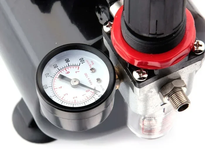
The gauge is the circular dial on the regulator. It shows you the current output pressure in PSI (pounds per square inch). When you look at the air compressor regulator diagram, the gauge is usually one of the first things labeled. It tells you exactly how much pressure is reaching your tool at any given moment.
Some compressors have two gauges. One shows the tank pressure. The other shows the regulated output pressure. The regulator diagram focuses on the output gauge. That is the one you watch when you adjust your settings.
The Regulator Knob
This is the big knob on top of the regulator. You turn it to change the pressure. In the air compressor regulator diagram, the knob is usually shown with an arrow indicating the direction to turn. Turning it clockwise increases the pressure. Turning it counterclockwise decreases the pressure.
Here is a quick tip. Always make small adjustments. Turn the knob a little bit, then wait a few seconds for the pressure to stabilize. Check the gauge. Then adjust again if needed. This prevents overshooting your target pressure.
The Pressure Relief Valve
This is a safety feature. If the pressure inside the regulator gets too high, the relief valve releases the excess air. You might hear a hissing sound when it activates. The air compressor regulator diagram marks this valve with a specific symbol, often an arrow pointing upward from a pipe.
The relief valve should never be blocked or modified. It is there to protect you and your equipment. If it keeps releasing air during normal use, that could mean the regulator is malfunctioning and needs inspection.
The Outlet Port
The outlet port is where the regulated air exits the regulator and flows to your tool. In the diagram, it is shown as a pipe or fitting connected to the regulator body. Make sure your hose is securely attached to this port. A loose connection here causes air leaks and pressure drops.
The Internal Spring and Diaphragm
Inside the regulator, there is a spring and a diaphragm working together. The spring pushes against the diaphragm to control the valve opening. When you turn the knob, you are adjusting the spring tension. This changes how much air can pass through to the outlet. The air compressor regulator diagram sometimes includes a cutaway view showing these internal parts.
How to Read and Use the Regulator Diagram
Reading the diagram is easier than you might think. Most diagrams follow a simple layout. The tank is shown on one side. The regulator is in the middle. The tool or hose is on the other side. Arrows show the direction of airflow.
Here is how to read it step by step:
- Find the tank on the left side of the diagram. This is where compressed air is stored.
- Locate the regulator in the center. Look for the knob, gauge, and relief valve labels.
- Follow the arrows to see how air flows from the tank through the regulator to the outlet.
- Check the gauge reading to understand what pressure level is shown at each stage.
- Identify the tool connection on the right side where the regulated air exits.
When you use your actual compressor, the physical setup mirrors the diagram. The tank pressure gauge sits near the tank. The regulator gauge sits on the regulator itself. Keeping the diagram handy while you work makes everything clearer.
If you are also curious about how much power your compressor uses, our article on how many watts does a small air compressor use gives you useful numbers to know.
Step-by-Step: Adjusting Your Regulator Pressure
Adjusting the pressure on your regulator is something you will do often. Here is the exact process in simple steps.
Step 1: Turn Off the Compressor
Safety first. Make sure the compressor is off before you touch the regulator. Wait for the tank to fully pressurize if you just started it. Watch the tank gauge to confirm the pressure has stabilized.
Step 2: Locate the Regulator Knob
Find the regulator knob on your machine. It is usually a large round dial near the output hose. On the air compressor regulator diagram, this is the part you interact with most often.
Step 3: Connect Your Tool
Attach your air hose to the outlet port. Then connect your tool to the hose. This way, you can test the pressure directly at the tool.
Step 4: Turn the Compressor On
Power on the compressor and let it build pressure. Watch the tank gauge until the motor stops. This means the tank is fully charged.
Step 5: Adjust the Regulator Knob
Now turn the regulator knob slowly. Turn clockwise to increase pressure. Turn counterclockwise to decrease it. Watch the regulator gauge as you adjust. Stop when the gauge shows the pressure your tool requires.
Step 6: Test and Confirm
Run your tool for a few seconds. Check that it operates smoothly. If the tool seems weak, the pressure may be too low. If it feels too strong or sounds unusual, reduce the pressure slightly.
For more on using your compressor with specific tools, see our article on how to use an air compressor for detailed guidance.
Common Regulator Problems and How to Fix Them
Even with proper care, regulators can develop issues over time. Here are the most common problems and simple fixes.
Pressure Drops Quickly
If the pressure falls fast after you set it, you might have a leak. Check all connections between the regulator, hose, and tool. Tighten any loose fittings. If the leak persists, the diaphragm inside the regulator may be damaged and need replacement.
Gauge Reads Inaccurately
A gauge that does not move or shows the wrong number is frustrating. First, make sure the gauge is not damaged physically. Sometimes debris gets behind the dial. If the gauge still reads wrong, it may need to be replaced. Gauges are inexpensive and easy to swap out.
Regulator Knob Feels Stiff
If the knob is hard to turn or does not turn at all, the internal spring may be stuck. Try applying a small amount of regulator-safe lubricant. If that does not work, the regulator may need to be disassembled and cleaned, or replaced entirely.
Air Leaks from the Relief Valve
A small hiss from the relief valve during normal operation is normal. A constant leak is not. This often means the regulator is set too high or the relief valve itself is worn out. Adjust the pressure down first. If the leak continues, replace the relief valve.
No Air Flow at All
If no air comes out of the regulator, check the inlet side first. Is the tank full? Is the hose kinked or blocked? If the inlet is clear, the regulator valve inside may be stuck closed. This usually requires professional inspection or regulator replacement.
Quick Tips for Beginners
- Always read your tool’s manual before setting the regulator. Each tool has a specific pressure requirement printed on it or in the manual.
- Never exceed the regulator’s maximum rating. Most home regulators handle up to 150 PSI output. Going beyond this is dangerous.
- Check the regulator gauge before every use. Make sure the pressure matches what your tool needs.
- Drain your tank regularly. Moisture builds up inside the tank and can affect regulator performance. Learn more about this in our guide on how often to drain your air compressor.
- Keep the regulator clean. Wipe it down after each use. Dirt and debris can work their way into moving parts.
- Label your pressure settings. If you use the same tool often, write down the ideal PSI. This saves you time next time you use it.
Expert Insight: Getting the Most from Your Regulator
Experienced users know that the regulator is more than just a knob and a gauge. It is the key to getting consistent, professional results from your compressor. Here are a few pro tips.
First, invest in a quality regulator. Cheap regulators lose accuracy fast. A good one stays precise even after years of use. Second, understand that pressure and flow are different things. The regulator controls pressure. The compressor controls flow, measured in CFM (cubic feet per minute). If your tool needs more air than your compressor can deliver, no amount of regulator adjustment will fix that. You need a compressor with a higher CFM rating. Check out our article on what does CFM mean on an air compressor to understand this better.
Finally, always bleed the system before making major pressure changes. This means briefly opening the regulator to release trapped air. It gives you a clean starting point and more accurate readings.
Conclusion
The air compressor regulator diagram is one of the most helpful tools you can have in your garage. Once you understand how to read it and use it, you gain full control over your compressor’s output. Every part of the diagram serves a purpose. The gauge shows you the pressure. The knob lets you adjust it. The relief valve keeps you safe. The outlet port delivers the air to your tool.
Remember to make small adjustments, check your connections, and never exceed your tool’s rated pressure. With these habits, your regulator will serve you well for years. Start by practicing on a simple project. Adjust the pressure, watch the gauge, and feel confident in your control. Soon, reading the regulator diagram will feel like second nature.
Now that you know how the air compressor regulator diagram works, you are ready to tackle any project with confidence. Grab your tools, set your pressure, and get to work. You have got this.
Frequently Asked Questions
What does the air compressor regulator diagram show?
The diagram shows every part of the regulator, including the knob, gauge, relief valve, outlet port, and internal spring. It also shows how air flows from the tank through the regulator to your tool. Think of it as a map that helps you understand how pressure is controlled and delivered.
How do I know what pressure to set my regulator to?
Check the label or manual for your specific air tool. Most tools list a recommended PSI right on the body or in the user guide. Set your regulator to match that number exactly. Never go above the tool’s maximum rated pressure.
Can I adjust the regulator while the compressor is running?
Yes, you can adjust the regulator while the compressor is running and the tank is pressurized. However, always make small turns and wait a few seconds between adjustments. This lets the pressure stabilize and prevents sudden surges that could damage your tool.
Why is my regulator gauge not moving?
A stuck gauge usually means either the gauge itself is broken or there is no airflow reaching it. Check that the compressor is running and the tank is pressurized. Also check for kinks or blockages in the hose. If everything else looks fine, the gauge likely needs to be replaced.
How often should I replace my air compressor regulator?
A good quality regulator can last for many years with proper care. Replace it if you notice constant air leaks, inaccurate gauge readings, or a knob that will not adjust properly. Regular maintenance and cleaning can extend its life significantly.
Is the regulator the same as the pressure switch?
No, they are different parts. The pressure switch controls when the compressor motor turns on and off based on tank pressure. The regulator controls the output pressure going to your tool. The air compressor regulator diagram focuses on the output side, while the pressure switch manages the tank side.