Simple Air Compressor Setup Diagram Everything You Need
A simple air compressor setup diagram shows you exactly how to connect every part of your compressor system. This guide walks you through each component, from the intake filter to the pressure regulator, so you can set up your compressor with confidence. You will learn the parts, the wiring, and the safety steps that matter most. Whether you are a beginner or a weekend DIYer, this guide makes the process easy and clear.
Setting up an air compressor does not have to feel overwhelming. A simple air compressor setup diagram breaks the entire process into easy-to-follow steps. When you can see how each part connects, the job becomes much less scary. This guide gives you that clarity. You will walk away knowing exactly how to build, connect, and maintain your compressor system like a pro.
Whether you are a homeowner tackling a garage workshop project or a hobbyist building a pneumatic system, this guide has you covered. We will cover every major component, walk through the setup process, and share tips that save time and money. Let us dive in and make your compressor setup a breeze.
Key Takeaways
- Understanding the diagram: A simple air compressor setup diagram helps you visualize the entire pneumatic system before you start.
- Know your parts: Each component, from the compressor tank to the pressure switch, plays a specific role in the setup.
- Follow the steps: A clear step-by-step process prevents mistakes and keeps your installation safe and efficient.
- Avoid common errors: Skipping the intake filter or mis wiring the motor can cause serious problems down the line.
- Maintenance matters: Regular checks on your compressed air line and moisture separator keep your system running smoothly.
- Safety first: Always follow compressor safety guidelines, especially around pressure gauges and electrical connections.
📑 Table of Contents
What Is a Simple Air Compressor Setup Diagram?
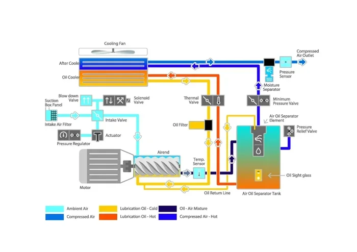
A simple air compressor setup diagram is a visual map of your entire compressor system. It shows how the compressor motor, tank, pressure switch, and air hose all connect together. Think of it as a blueprint that tells you where every piece goes.
These diagrams are incredibly helpful for a few reasons. First, they help you understand the flow of air from the intake to the output. Second, they show you the correct wiring and plumbing paths. Third, they make troubleshooting much easier when something goes wrong.
Why You Should Always Use a Diagram
Many people skip the diagram and just start connecting parts. That approach often leads to leaks, wrong wiring, or safety hazards. A simple air compressor setup diagram removes the guesswork. You can see the big picture before you touch a single tool or wrench.
Here are a few benefits of using a setup diagram:
- Clarity: You see the full system at a glance.
- Safety: You avoid dangerous misconnections.
- Efficiency: You set up faster with fewer mistakes.
- Troubleshooting: You can trace problems back to their source.
Even if you buy a pre-assembled compressor, reviewing the diagram helps you understand how the system works. That knowledge comes in handy when you need to make repairs or upgrades later.
Key Components of Your Air Compressor System
Before you follow a simple air compressor setup diagram, you need to know what each part does. Every component in the system plays a specific role. Let us break them down one by one.
Compressor Motor
The compressor motor is the heart of the system. It powers the pump that draws in air and compresses it into the tank. Most home and workshop compressors use either a single-phase or three-phase motor. Single-phase motors are common for DIY setups and small garages. Three-phase motors are used in industrial environments where more power is needed.
When you look at a simple air compressor setup diagram, the motor is usually shown at the beginning of the airflow path. It drives the entire pneumatic system forward.
Compressor Tank
The compressor tank stores the compressed air. It acts as a reservoir so the motor does not have to run constantly. When you pull air through your tools, the tank supplies it at the right pressure. Tank size matters a lot. A larger tank means longer run times between motor cycles.
Most home setups use tanks between 6 and 60 gallons. Your simple air compressor setup diagram will show the tank connected directly to the motor output and the pressure switch.
Pressure Switch
The pressure switch controls when the motor turns on and off. It monitors the air pressure inside the tank. When the pressure drops below a set level, the switch tells the motor to start. When the pressure reaches the upper limit, the switch shuts the motor off. This prevents over-pressurization and saves energy.
On a simple air compressor setup diagram, the pressure switch sits between the tank and the motor. It is a small but critical component that protects the entire system.
Pressure Regulator
The pressure regulator lets you adjust the output pressure for your tools. Not every tool needs the same pressure. A nail gun might need 90 PSI, while a paint sprayer might need only 40 PSI. The regulator sits on the output line and lets you dial in the exact pressure you need.
Always install a pressure gauge next to the regulator. This helps you monitor the output pressure in real time. Many simple air compressor setup diagram designs include both the regulator and the gauge as a single unit.
Intake Filter
The intake filter cleans the air before it enters the compressor. Dust, debris, and moisture can damage the motor and reduce the quality of your compressed air. A good intake filter extends the life of your entire system.
Do not skip this part. On a simple air compressor setup diagram, the intake filter is always at the very start of the airflow path. It sits on the air inlet and protects everything downstream.
Air Hose and Quick Connect Fittings
The air hose carries compressed air from the regulator to your tools. Quick connect fittings make it easy to switch between tools without dealing with messy threaded connections. These fittings are a small detail that makes a huge difference in daily use.
Your simple air compressor setup diagram will show the air hose running from the output valve to the quick connect fitting. From there, you can plug in any compatible pneumatic tool.
Moisture Separator
A moisture separator removes water from the compressed air. When air is compressed, it heats up and holds moisture. As it cools, that moisture condenses into liquid water. Without a separator, that water can damage your tools and affect your work quality.
Many simple air compressor setup diagram setups include a moisture separator between the tank and the regulator. This ensures dry, clean air reaches your tools every time.
Step-by-Step Setup Process
Now that you know the parts, let us walk through the actual setup. Following a simple air compressor setup diagram step by step makes this process smooth and safe.
Step 1: Choose Your Location
Place your compressor on a flat, stable surface. Avoid areas with excessive moisture or extreme temperatures. Good ventilation is important because the motor needs airflow to stay cool. Keep the compressor away from flammable materials and busy walkways.
Quick Tip: Place a rubber mat under the compressor to reduce vibration and noise.
Step 2: Install the Intake Filter
Attach the intake filter to the air inlet on the compressor. Make sure the connection is tight and free of leaks. The filter should face outward to draw in clean air from the surrounding environment.
Check the filter regularly. A clogged intake filter forces the motor to work harder and reduces efficiency. This is one of the most overlooked parts of simple air compressor setup diagram maintenance.
Step 3: Connect the Compressor Tank
Secure the tank to the compressor base using the mounting bolts. Connect the air line from the motor pump to the tank inlet. Use the fittings provided with your compressor and tighten them firmly. A loose connection here will cause air leaks and reduce system performance.
Most simple air compressor setup diagram guides recommend using Teflon tape on threaded connections. This creates a tighter seal and prevents slow leaks over time.
Step 4: Wire the Pressure Switch and Motor
This step requires some electrical knowledge. Connect the pressure switch between the motor and the power supply. The switch should be wired according to the manufacturer’s instructions and local electrical codes.
If you are not comfortable with electrical work, hire a licensed electrician. Safety always comes first when dealing with compressor wiring. A simple air compressor setup diagram will show the correct wiring path, but an expert should handle the actual installation.
Step 5: Install the Pressure Regulator and Gauge
Attach the pressure regulator to the tank output valve. Connect the pressure gauge right after the regulator. This lets you monitor and adjust the output pressure for different tools.
Set the regulator to the pressure your tool requires. Most pneumatic tools list their recommended PSI on the tool body or in the user manual. Adjust the regulator slowly and check the gauge as you go.
Step 6: Attach the Air Hose and Fittings
Connect the air hose to the regulator output. Attach a quick connect fitting to the hose end. This makes it easy to swap tools without shutting down the system. Run the hose to your workspace and secure it with hose clamps or hooks to keep it off the floor.
Pro Tip: Coil any excess hose length and hang it on a wall mount. This keeps your workspace tidy and prevents tripping hazards.
Step 7: Add a Moisture Separator (Optional but Recommended)
Install the moisture separator between the tank output and the regulator. This catches condensation before it reaches your tools. Drain the separator regularly to keep it working effectively.
Many simple air compressor setup diagram setups include this step because dry air makes a big difference in tool performance and longevity.
Common Setup Mistakes to Avoid
Even with a clear simple air compressor setup diagram, mistakes can happen. Here are the most common errors people make when setting up their compressor systems.
Skipping the Intake Filter
Some people leave the intake filter off to save money or because they think it is unnecessary. This is a big mistake. Without a filter, dust and debris enter the compressor motor and cause premature wear. Your compressed air line will also carry contaminants that can damage pneumatic tools.
Undersizing the Air Hose
A hose that is too narrow creates friction and reduces airflow. This means your tools run at lower pressure than they need. Always match the hose diameter to the regulator output and the tool requirements. Most home setups work well with a 3/8-inch or 1/2-inch hose.
Ignoring Electrical Requirements
Every compressor motor has specific electrical requirements. Using the wrong gauge wire or an undersized circuit breaker can cause overheating or electrical fires. Check the motor nameplate for voltage and amperage specifications before you wire the system.
Forgetting to Check for Leaks
Even a small leak in the compressed air line wastes energy and reduces pressure. After you complete the setup, pressurize the system and listen for hissing sounds. You can also use soapy water on connections to spot leaks. Bubbles will form where air is escaping.
Not Understanding the Pressure Switch
The pressure switch controls the on-off cycle of the motor. Setting it incorrectly can cause the motor to short-cycle, which wears out the motor quickly. Always set the cut-in and cut-out pressures according to the manufacturer’s recommendations.
Overlooking the Moisture Trap
Water in the compressed air line is a silent killer. It rusts internal tool components and ruins paint jobs. Many DIYers skip the moisture separator during setup. Do not make that mistake. Your simple air compressor setup diagram should always include a moisture management plan.
Tips for Optimal Compressor Performance
Once your compressor is set up, a few best practices will keep it running smoothly for years. These tips go beyond just following a simple air compressor setup diagram and help you get the most from your system.
Check Oil Levels Regularly
If your compressor uses oil lubrication, check the oil level before each use. Low oil causes increased friction and heat, which shortens the motor life. Change the oil according to the manufacturer’s schedule, usually every 500 hours of operation.
Drain the Tank After Every Use
Condensation builds up inside the tank over time. Open the drain valve at the bottom of the tank after each use to release accumulated moisture. This prevents rust inside the tank and keeps your compressed air dry.
Keep the Area Clean
A clean compressor runs cooler and lasts longer. Wipe down the exterior regularly and keep the intake area free of dust and debris. Good housekeeping around your compressor setup is one of the easiest ways to extend its lifespan.
Inspect Hoses and Fittings Monthly
Over time, hoses can crack and fittings can loosen. Inspect all connections once a month and tighten anything that has worked loose. Replace any hose that shows signs of wear or damage. This small habit prevents air leaks and keeps your pneumatic system efficient.
Use the Right Tools for the Job
Every pneumatic tool has a specific pressure and airflow requirement. Using a tool that demands more air than your compressor can deliver will cause performance issues. Check the tool specifications against your compressor output before you start a job.
Consider a Second-Stage Regulator
If you use multiple tools at the same time, a second-stage regulator can help maintain consistent pressure. This is especially useful in workshops where several people share the same compressor system. A simple air compressor setup diagram can be upgraded to include a second-stage regulator without major modifications.
Troubleshooting Your Air Compressor Setup
Even with the best simple air compressor setup diagram, issues can arise. Here are some common problems and how to fix them.
Compressor Runs but No Air Comes Out
This usually means there is a blockage in the air line. Check the intake filter first. A clogged filter restricts airflow and prevents the compressor from delivering air. Next, inspect the regulator and hose for any kinks or obstructions.
Pressure Drops Quickly
A rapid pressure drop often points to a leak in the system. Check all fittings, hose connections, and the tank valve. Use soapy water to identify the exact location of the leak. Tighten or replace the affected component.
Motor Cycles On and Off Too Frequently
This is called short-cycling and it usually means the pressure switch settings are too narrow. Widen the pressure band by adjusting the cut-in and cut-out screws on the switch. If the problem persists, the pressure switch itself may need replacement.
Unusual Noises During Operation
Grinding, rattling, or knocking sounds are never normal. They often indicate loose components, low oil levels, or a failing motor bearing. Turn off the compressor immediately and inspect the source of the noise before running it again.
Moisture in the Air Output
If you notice water coming out of your air tools, the moisture separator may be clogged or missing. Check the separator and drain it thoroughly. If the problem continues, consider adding an inline air dryer to your setup for extra moisture removal.
Conclusion
A simple air compressor setup diagram is one of the most valuable tools you can have when building or upgrading your compressor system. It gives you a clear roadmap from start to finish, covering every component from the intake filter to the air hose. By following the steps in this guide, you can set up your compressor safely, efficiently, and with confidence.
Remember to check each part of your system regularly. Replace filters, drain the tank, and inspect hoses to keep everything running at peak performance. A well-maintained compressor system delivers consistent power and saves you time and money in the long run.
Take what you have learned here and apply it to your own setup. Whether you are building a new pneumatic system from scratch or improving an existing one, a solid understanding of your simple air compressor setup diagram makes all the difference. Get your diagram, gather your tools, and get started today.